Blog

How to Choose a 35VHC Cryogenic Tank?

Choosing a 35vhc cryogenic tank starts with a clear question: what cryogen will it store, and under what conditions? The product name alone may not reveal its full design limits. Confirm the exact model designation, usable capacity, operating pressure, and intended service with the manufacturer’s current data sheet. Details matter.

The tank’s materials, insulation system, valves, and instruments should suit the specified cryogen and operating environment. Ask how the design manages heat transfer, pressure changes, and routine filling. A supplier should provide traceable technical documentation and explain inspection and maintenance requirements. Do not rely on a generic capacity figure; usable volume can differ from total vessel volume. Small distinctions matter here.

Installation also deserves attention. Check the available footprint, access for delivery, connection locations, and compatibility with site equipment before placing an order. A specification can look complete and still leave one awkward gap: the actual service conditions. Review that gap with a qualified cryogenic-equipment professional, especially if the tank will operate in a demanding environment. It is worth slowing down. This guide outlines practical questions to ask, documents to compare, and design features to verify when evaluating a 35vhc cryogenic tank. It cannot replace the manufacturer’s specifications or a site-specific engineering review, but it can help buyers make a more informed shortlist.
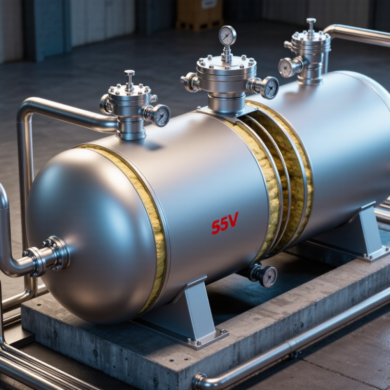
How to Choose a 35VHC Cryogenic Tank?

Identify the fluid: N₂ boils at 77 K, O₂ at 90 K, and LNG near 111 K

Before choosing a 35VHC cryogenic tank, identify the fluid and its operating temperature. At atmospheric pressure, nitrogen boils at about 77 K, oxygen at 90 K, and LNG near 111 K. These temperatures are reference points, not complete operating specifications. Pressure changes boiling behavior, and LNG’s composition can shift its temperature range.

That matters. A tank intended for one cryogen should not be assumed suitable for another. Confirm the vessel’s rated service, pressure range, insulation design, and material compatibility with its technical documentation. For oxygen service, cleanliness is especially important because oils and other contaminants can create serious hazards. LNG systems also need components suited to the fuel’s composition and vapor behavior.

Look beyond the tank nameplate. Check the expected fill level, transfer conditions, relief system, and temperature at the connection points. A frosted valve or cold vapor plume can reveal heat ingress, but appearance alone cannot confirm safe operation. Small differences count. I would verify the fluid and pressure requirements with a qualified cryogenic engineer before specifying the vessel; it is easy to focus on the boiling point and miss the rest.

Size usable capacity with expansion ratios: LN₂ ~694:1; LOX ~860:1

A 35VHC cryogenic tank should be sized around usable liquid capacity, not its advertised gross volume. When liquid warms and vaporizes, LN₂ expands roughly 694 times by volume; LOX expands about 860 times. These are approximate gas-to-liquid ratios, based on specified reference conditions. Check the supplier’s stated conditions before using them in a design calculation.

For a simple estimate, multiply the required liquid volume by the relevant ratio to understand the potential gas volume. Then work backward, allowing for fill limits, unusable heel, operating pressure, and expected boil-off. A nominal 1,000-liter tank does not necessarily provide 1,000 liters of working capacity. That matters. A small mismatch can affect delivery schedules and reserve planning. Keep the calculation tied to actual operating conditions, including withdrawal rate and ambient heat exposure. Insulation slows heat transfer; it does not stop it. Expansion figures are useful, but they are not a substitute for a verified tank specification. I would revisit the estimate after checking the intended fill level and venting assumptions, since those details are easy to overlook in an early sizing pass.

Set design pressure and verify ASME BPVC Section VIII or EN 13458 compliance

For a 35VHC cryogenic tank, define the design pressure from the intended service, operating range, and credible pressure-rise scenarios. Do not guess. Normal operating pressure alone is not enough: filling conditions, heat leak, trapped liquid, and pressure-building equipment can all affect the required rating. Relief-device settings must remain within the vessel’s permitted limits and be coordinated with the full pressure-protection design. Small details matter.

Choose the governing construction code before approving drawings. ASME BPVC Section VIII and EN 13458 have different requirements for design, fabrication, inspection, and documentation; they are not interchangeable checklists. Confirm which code applies with the responsible design engineer and the relevant authority for the installation. Then verify that materials, weld procedures, examination, and pressure testing suit cryogenic temperatures. A material acceptable at room temperature may behave differently when cold. Review the nameplate and calculation records against the selected code, not just the purchase specification. This review can feel repetitive, and some project assumptions may need correction late in the process. That is better than treating a stated design pressure as proof of compliance.

Compare insulation heat leak, boil-off rate, and required holding time

A 35VHC tank should be compared by measured heat leak, not insulation thickness alone. Ask for heat ingress in watts, test conditions, and whether the figure includes valves, supports, and piping. Small thermal bridges matter. A warm valve can quietly raise daily losses. GIIGNL’s LNG custody-transfer guidance discusses boil-off accounting; conventional LNG carrier design figures are often around 0.10–0.15% of cargo per day. That is a transport benchmark, not a guaranteed rate for a stationary tank.

Convert heat leak into boil-off for the actual fluid: daily vapor mass is approximately heat leak × 86,400 seconds, divided by latent heat. NIST lists nitrogen’s latent heat near its normal boiling point at about 199 kJ/kg. For example, a 10-watt heat leak implies roughly 4.3 kg of nitrogen vapor per day, before operating effects. Check the supplier’s calculation against test data. The assumptions can be optimistic.

Then estimate holding time from usable liquid inventory and daily boil-off, allowing for heel, pressure limits, and venting. Request figures at your expected fill level and ambient temperature, not only ideal conditions. Compare the same fluid and operating basis. A few extra days on paper may disappear after repeated deliveries and partial fills. The estimate is useful, but never perfect.

Match materials, relief devices, and transport approvals to the intended service

Choose the tank for the actual fluid and duty, not just the “35VHC” label. Confirm capacity, maximum allowable working pressure, design temperature, and expected fill and unloading conditions. Methane and nitrogen impose different temperature demands: NIST lists normal boiling points of about 111.7 K and 77.4 K, respectively. The inner vessel, piping, valves, and seals must all suit the selected fluid. Stainless steel is common in cryogenic service, but grade, weld quality, and insulation details still need verification. Small details matter.

Relief devices should match credible heat-inleak and pressure-rise scenarios, with set pressure coordinated to the vessel rating. Check vent routing too; a safe valve can still create a hazard if discharge reaches workers or ignition sources. The U.S. Department of Energy notes that liquefaction reduces natural-gas volume by roughly 600 times, underscoring why containment and pressure control matter during transport. Treat that figure as context, not a sizing rule. For a road, rail, or sea route, verify the tank’s current approvals and inspection status against the applicable transport rules, such as DOT, ADR, or IMDG requirements. I would not assume one approval covers every route. Before purchase, compare the nameplate, relief-device certificates, material records, and intended service conditions; paperwork can be easy to overlook.

How to Choose a 35VHC Cryogenic Tank? - Match materials, relief devices, and transport approvals to the intended service

Selection dimension What to match to the service Practical checks
Product and operating conditions Identify the exact refrigerated liquefied gas—such as liquid nitrogen, oxygen, argon, or LNG—and its design pressure, normal pressure range, filling limits, and expected temperature. Confirm the product’s compatibility, required delivery pressure, maximum permitted filling mass, and applicable operating instructions. Do not infer capacity or pressure from “35VHC” alone.
Capacity and payload Choose usable liquid capacity based on the product density, permitted filling ratio, route limits, and required delivery volume. Cryogenic liquids expand substantially when warmed and vaporized. Check the nameplate’s water capacity, maximum gross mass, tare mass, payload, and product-specific filling limits. Verify axle, rail, and container gross-weight limits for the intended route.
Inner vessel and wetted materials Austenitic stainless steels, commonly grades such as 304L or 316L, are used in many cryogenic vessels because they retain toughness at low temperatures. Material suitability depends on the product, design, fabrication, and applicable code. Review material certificates, design minimum temperature, weld procedures, and compatibility of valves, seals, and piping. Oxygen service requires materials and cleanliness controls suitable for oxygen; LNG service requires product-specific compatibility review.
Outer shell and insulation A vacuum-insulated vessel typically uses an inner pressure vessel, an outer shell, and an insulating space that may include multilayer insulation. The outer shell protects the insulation system; it is not a substitute for the inner vessel’s pressure rating. Check insulation performance, vacuum-monitoring provisions, allowable heat leak, hold time, and inspection or repair arrangements. Confirm that the specified hold time fits the full loading, transit, and unloading cycle.
Pressure-relief protection The design generally requires pressure-relief protection sized and set for the vessel and service. Depending on the design and regulations, this can include relief valves and a separate protective device, such as a rupture disc. Verify set pressure, certified capacity, discharge routing, device arrangement, inspection interval, and any required isolation safeguards against the approved design. Never block, cap, or alter a relief path in service.
Valves and connections Select liquid, vapor, vent, fill, and pressure-building connections to suit the transfer method and facility interface. Connection type, material, and configuration must be compatible with the gas and the approved tank design. Confirm connection standards, valve ratings, flow capacity, labeling, caps or plugs, and safe access. Ensure operating procedures address trapped liquid, frostbite risk, oxygen enrichment, or flammable-gas hazards as applicable.
Transport approval Required approvals depend on the tank’s construction, product, and transport modes. International journeys may involve applicable dangerous-goods rules such as ADR/RID, IMDG, or the relevant national regulations; a tank-container design may also be subject to applicable ISO and container-safety requirements. Request the current approval documents, inspection records, identification plates, and product authorization. Check that approvals cover the exact tank, gas, pressure, route, and mode—not merely a similar model.
Inspection and service life Inspection and test requirements vary with the governing code, transport approval, tank type, and jurisdiction. Vacuum insulation, pressure equipment, and transport fittings may have different inspection needs. Review the inspection history, due dates, repair records, vacuum condition, corrosion or impact damage, and availability of qualified service facilities before purchase or lease.
Final suitability check The best tank is the one whose certified design and operating limits match the actual product, transfer system, journey, and receiving facility. Have the tank documentation reviewed by the responsible design authority or qualified dangerous-goods professional before service. Treat the nameplate and approved documentation as controlling; do not rely on a generic “35VHC” description.

Note: Regulatory requirements and equipment specifications vary by jurisdiction and application. Confirm current requirements with the relevant competent authority and the tank’s approval documents.